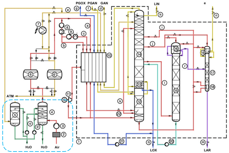
In a cryogenic air separation plant, air is separated into its components based on their boiling points at a very low temperature. The process flow diagram is rather complex and challenging for an undergraduate chemical engineering student. It consists of a very tight material and heat integration.
My superior used to say, “During the learning process, it is better to color the process flow diagram based on the fluid service,” and I still hold his advice up to this day. In a simplified way, the process consists of 2 main parts: warm section (pre-treatment) and cold section (rectification and liquefaction). We will look together at the process step-by-step.
Warm Section (Filtration, Compression, and Cooling)
(Heinz-Wolfgang Häring, 2008)
Atmospheric air is filtered in a feed air filter to remove the solid (dust) impurities. This is to prevent any impingement damage to the feed air compressor’s internal parts. Then, it is pressurized up to a rated pressure (~4.8 – 5.2 bar.G) by a feed air compressor. The unit provides a main energy source for the separation.
The hot compressed air (~105℃) is then cooled by cooling water (~32℃) and chilled water (~7℃) in a direct contact air cooler, down to a temperature of ~8 – 15℃. Because of a lower temperature, most of the water vapor content in the atmospheric air is condensed and removed. It will help to reduce the adsorbents’ working load during a subsequent purification process. A demister pad is provided at the top part of the direct contact air cooler to prevent any water entrainment.
To generate chilled water, a water cooling tower is employed, where the cooling water comes into a counter-current contact with the waste nitrogen gas from the cold box. Evaporative cooling happens in this process. If the cooling medium is not sufficient, an additional water chiller unit could be added.
Reference
Heinz-Wolfgang Häring. (2008). Industrial Gases Processing. John Wiley & Sons.

Leave a comment